For my research project I wished to focus on crafting mechanical joints in a realistic and functional manner. I've always loved making robots and other mechanical creations, but the details of how everything fit together was always guess work. When designing details, I would focus more on what looked cool, with random sci-fi detailing and hidden connection points. Through this research, I hope to make more informed decisions when crafting mechanical characters. As a game developer, functionality is important to me as well. In terms of useability, I wish to take my characters as far as I can take them, potentially up until they are a playable character. Ensuring their joints move in a realistic way without breakage or clipping will make my life and the lives of my teammates easier, as well as make for stronger portfolio pieces to viewers who possess a knowledge of proper engineering.
I will start this article by outlining several types of mechanical joints. I will focus on their basic construction, and how to craft them in 3D, as well as how this type of workflow may differ from real-world construction. I will also outline the strengths and weaknesses of using each joint, and where each method can be utilized. I will then discuss some of my projects from my time at FIEA, and how my research on mechanical joints has helped me construct each key piece of them. For each project, I will also discuss how each was rigged and exported to Unreal Engine for use in games.
Ball and Socket Joints
These joints, like most examples, consist of a male and female piece that socket into each other. For future reference, the male piece usually is usually inserted in some manner into the female piece. In this case, the male piece has a spherical pivot point that fits snugly into a concave opening on the female piece. The male piece is not connected to a single point, instead rotating freely while its position is limited by the socket. With this, ball joints have the widest freedom of rotation compared to the other joints in this list, able to rotate in all axes with minimal resistance. With their simple construction, ball joints are one of the easiest to create, as well as being one of the most useful.
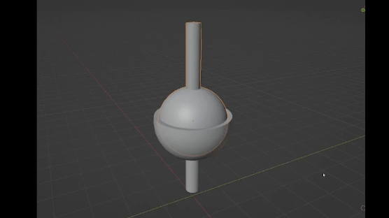

Ball joints have some limitations. The male piece needs to fit within a socket, which can vary in size. Realistically the socket needs be larger than half the size of the ball to completely lock the male piece inside. Because the ball piece needs a connecting point, this will collide with the socket if the joint is rotated too far, limiting its rotation. This can be mitigated with a notch in the socket that allows the connecting pin to rotate into the opening, giving a much greater degree of rotation on one axis compared to others. Usually a ball socket can only have one of these notches on either side before the mechanics of the socket is compromised. Ball joints can be used in any location on the body of a mechanical character. Most often, they are seen in shoulder and neck, where a wide range of rotation is necessary. In humans, the shoulder and hip connections are actual ball joints.

Most joints on a mechanical characters can be created using ball joints, however there are other considerations for why a modeler should be wary of overusing them. In reality, ball joints are not the strongest forms of connection, and are susceptible to issues such as breakage and rust. Simpler forms of joints, such as hinge joints are more common, so when modeling pieces where a ball joint is not necessary, other design choices should be considered when trying to capture realism. Secondly, ball joints are common in toys and action figures, as they do not need to withstand such strong forces. Utilizing too many ball joints in a mechanical model can make it look more toy-like than intended.

Hinge Joints


Hinge joints are very common in mechanical characters and props alike. In many circumstances, especially in props, a single degree of rotation is all that is needed. Hinge joints are perhaps the most identifiable mechanical joint, and many would expect to see one or more hinge joints in a mechanical character. They also tend to fit together precisely, so they can be the most aesthetically pleasing form of joint. They are most often seen in elbow, knee, and finger joints on robotic characters. It is advised to work with hinge joints rather than avoid them. When used smartly, they can be a simple and effective way to construct mechanical forms, and with some of the methods discussed here, they do not have to be as restrictive as perceived.
Swivel Joints
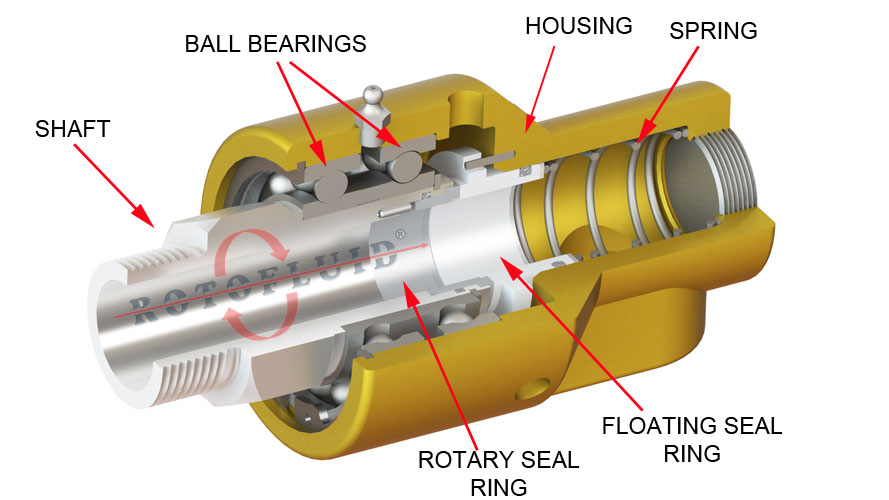
Swivel joints, similar to hinge joints, provide a single axis of rotation, although in a more lateral manner. The construction usually consists of a female piece with an opening and a male piece that fits within, rotating along a perpendicular axis. Unless a separate piece blocks the rotation of either piece, swivel joints can usually rotate a full 360 degrees. While this type of joint in real world engineering most likely requires complex internal mechanisms to keep the two halves together and rotating freely, it is very easy to fake this connection in 3D modeling. Usually only a small portion of the male extrusion is visible between the two halves, so in reality the rest of the male piece and the opening of the female piece do not need to exist to sell the appearance of a swivel joints. In fact, these types of joints tend to be invisible until a swivel rotation actually occurs.


Prismatic/Sliding Joints
Sliding joints are connections based on relative translation as opposed to rotation. Also known as a prismatic joint, they differ from revolute joints, which include all of the previously mentioned joints. Most often they involve a male joint that is attached to a female joint but moves relative to its location on a fixed axis or track. A common use case is a piston, where the male joint is attached within the female piece similar to a swivel joint. The male joint can extend out of the female, meaning that both pieces must be appropriately elongated and allow for the proper range of extension. The translation can also occur along a track, in which case the female piece will have an inset track, and the male piece will have a connecting pin or rail that locks to the track and can travel across it. In special cases, this track can actually be curved, allowing for complex translation across two axes. When used in conjunction with other connection points and swivels, these curved tracks can be used to create highly specific rotation across a joint chain.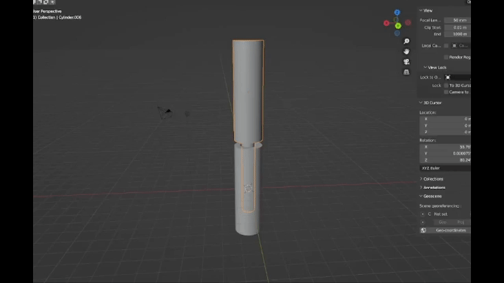


Chains and Treads


Finding Mechanical Joints Close to Home
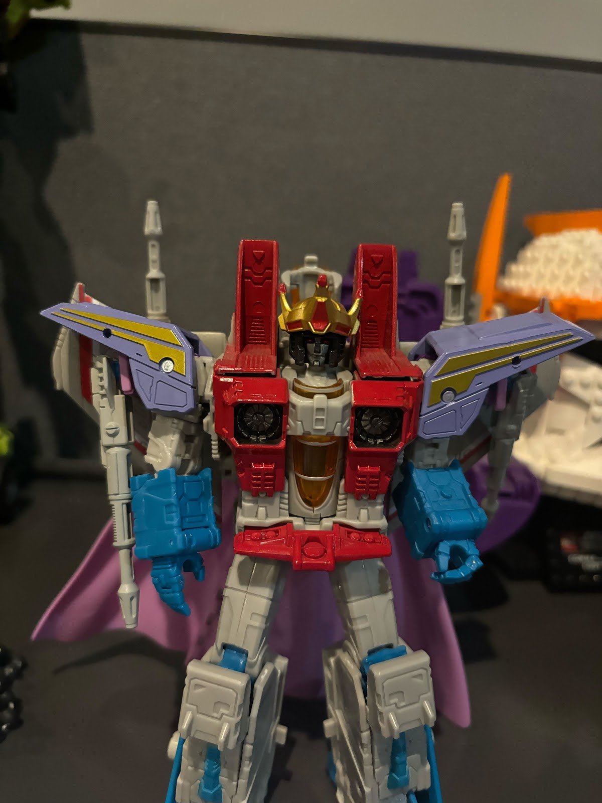
A key part of my research was finding mechanical joints out in the real world, and thankfully I knew right where to look, directly in front of me on my desk. I'm a big fan of Transformers, LEGO, Gundam, and other toy lines related to mechanical characters. As the franchise reaches its 5th decade on toy shelves, Transformers in particular has reached new heights in engineering principles. I can observe the figures I own to discover how these manufacturers crafted joints that are the right combination of aesthetically pleasing, flexible, and strong.


Hip joints are one of the areas I knew would be challenging going into this project. The waist of any mechanical character must support a lot of weight and keep the upper torso and arms upright. Because of this most hip joints are not constructed with ball joints, which are known to be loose, and can loosen more over time. The most common hip joints, as they are known in action figure communities, are universal joints. While in engineering, this name refers to a different type of joint that allows for rotation across a bending joint chain, in this case it simply refers to a combination of a swivel joint and a hinge joint. The swivel joint allows for the leg to move forward and back, while the hinge allows the leg to move in and out. With both axes the leg can move in any direction necessary. Is is easier to maintain friction in hinge and swivel joints, preventing the torso from falling backwards or forwards. Shoulders are also often constructed with universal joints.


Elbows are usually constructed with hinge joints, but humans do have the ability to swivel their wrists and forearms, which involves the inversion of the ulna and radius. To simulate this a separate swivel joint can be constructed lower on the forearm. On larger figures, such as Devastator here, the elbows, along with other body parts, are constructed with ratcheting joints. These are hinge joints with teeth on the pivot point. To rotate the joint further, force must be applied to push the teeth past each other, usually resulting in a jolt with a distinct clicking sound. This way, additional force that is stronger than gravity must be applied to rotate the joint. In this case, it prevents the elbows from falling when Devastators arms are bent in particular poses.
For the hands, ball joints are often utilized for the wrist, giving a wide range of expression, as well as at the base of the fingers, allowing them to spread apart. Ball joints can also be used for the finger segments, but realistically fingers cannot bend in that way. Here hinge joints are more widely used. Palms are not usually as complex as real human palms, not requiring the same level as flexibility. They can be just a flat piece in which the fingers connect to.


Mechanical Joints and Me (My Projects)
With a working knowledge of mechanical joints in real world engineering, toy design, and 3D modeling, I began work putting this knowledge into practice. In semesters 2 and 3 of FIEA, I developed four projects focused on hard surface modeling, all of which include mechanical joints and functional elements.
Laserbeak


The second project of semester 2 was focused on hard surface modeling, and I chose a doozy of a project. I wanted to recreate a Transformers toy, and make it actually transform. After ruling out the larger figures, I settled on Masterpiece Laserbeak, a small accessory of the larger Masterpiece Soundwave figure. Laserbeak is a bird that transforms into a mini-cassette across 7 steps. I began the process by creating all the pieces in cassette form out of simple planes and establishing pivot points. This way I ensured all the pieces fit together properly and could transform into bird form. After going through this frustrating process using only online references, I had my mom send me the figure from home in New York. Having it in hand made things much easier.

Laserbeak is mostly constructed using hinge joints; single hinges for the neck, head, and legs, and double hinges for the wings and engines. Swivel joints are used for the base of the wings, and the feet. The former allows the sides of the cassette to split and form the bird's wingspan. Because the cassette opens up entirely during transformation, there was not much hiding I could do. I had to model every part of the toy, inside and out. My attention to detail went so far I actually modeled the metal pins connecting each of the hinge joints on the model. In hindsight, these proved to be completely hidden in the tight joints, and I would have save a lot of time making UVs if I excluded the interior portion and just left the indents on the exterior of the model.


This model was not rigged, instead the pieces were exported individually and transformed in engine using an actor sequence. I was afraid to try rigging in Maya. In hindsight I should have just manned up and did it to avoid the future headache.

These challenges were mitigated by the fact I had a very clear reference to work from, so there was little guesswork involved in the construction of the joints. I learned a lot by working on such a realistic project, and it gave me the confidence to develop more complex pieces. I did decide to transition away from Maya, however, which proved to be a good decision.
Mr. Drills

My final project for semester 2 was a robotic character. This was a potential enemy developed for our capstone project, CHROMA, affectionately dubbed Mr. Drills. Eric Wiley made a sketch of him in pre-production that we all thought was pretty neat. While we didn't have the scope to include him, I wanted to make him anyways. I expanded on Eric's initial sketch, giving him more complex mechanical parts. I wanted to use this character to learn more about mechanical joints, as well as how to create and animate tank treads.


The modeling process was pretty smooth for Mr. Drills, but in some ways I took the easy way out when it came to constructing his joints. Most of his connections utilize ball joints, including his shoulders, head, abdomen, chest, and hips. While I feel I hid them well, and they do provide him a great deal of flexibility, he does run into the problem of looking somewhat like a toy, and I wish I'd experimented more with hinge and swivel joints.


The elbows do use a hinge joint, along with a piston which would realistically pull on the drill portion to raise it up. The bone for the piston uses a "Track To" constraint, which makes the bone point at another object, in this case an empty locator attached to the drill bone. In this case the other end of the bone is hidden within the drill, but if the opposite connection was visible, another Track To constraint would be needed to point that connector at the origin of the piston, ensuring the male and female joints stay aligned with each other.

The tank treads, which are made up of 18 objects, were constructed using an Array and Curve Modifier. Making an Array meant that I did not have to duplicate each piece, and any changes I made to one would effect the others. A Curve Modifier on top of that made each new piece conform to a bezier curve I created as they were instantiated. For a realistic shape, the treads needed to curve around a set of anchor points, one at each lower corner, and one on top which also acted as the sprocket for the mechanism. This created a skewed triangle shape. With some parameter tuning, I had a complete closed loop for the tanks treads.

To make the treads actually work, I used a Transformation Constraint. In Blender, this allows transformation on one object in relation to the transformation of another object. This can be used for the same type of transform, such as rotation to rotation, or different ones, like location to rotation. In this case the rotation of the sprocket is mapped to the location of the tank treads. Because the treads are still attached to the curve, moving them rolls them along its path. I also mapped the rotation of the other anchor wheels to the rotation of the sprocket. Using this constraint can be difficult as it's usually a lot of guess work figuring out which numbers are needed to achieve the desired effect, an it can take a lot of practice setting up the correct axes and directions.


Because the treads were not constructed with rigged bones, I had to export them separately as alembic files after I made a looping animation of their movement. This I was able to export to Unreal and attach to the rest of Mr. Drill's skeletal mesh. Alembic files can be quite large and un-performant in engine, but are a simple way to utilize complex mechanical animation.
For the actual bones of this project, as well as any other mechanical character, accuracy is very important. There is no wiggle room for pivot points, so bones have to be aligned very carefully. In Blender, I used a simple method to achieve this. Placing the 3D cursor in exact positions using Shift S > Cursor to Selected, it can be placed on the exact pivot of an object, face, edge, or vertex, as well as the center point of a combination of selections. Then the start or end of a bone can be selected and moved to that exact position using Shift S > Selection to Cursor.

PRISM

My most substantial contribution to CHROMA was modeling and rigging the game's final boss, PRISM, a giant super-computer turned flying death machine. In terms of anatomy, PRISM is not too complex, in order to make his battle mechanics not too difficult to design. He does not have legs or a head, just a giant body with a face and arms. However he has a lot of small and complex mechanisms on each of his different sections.
For the elbows I used a universal joint, a hinge attached to a swivel. The swivel in hidden within the bicep armor, so the connection is not represented, but the flexibility remains. On the laser cannons, I included pistons that extend in and out of the armor plating, with circular openings created with booleans. These activate rapidly to indicate when he is about to attack. On the front of the lasers, I included coverings that flip open to reveal the cannon barrel. Because I wanted the covering to remain flat after they opened, I used a double hinge joint, along with a Rotation Constraint. As the hinge opens, the cover matches the rotation of the laser cannon, shifting up but remaining level. This motion almost resembles a sliding joint with a slightly curved path.

PRISM's face is made up of multiple eyes, covered by a screen that displays his AI generated persona. This screen splits apart when PRISM enters battle mode. For this to work, the screen pieces had to be very flexible, and include the ability to compress tightly against his body. So I created a long chain of hinge joints that can accordion against each other. At each end of the chain is a swivel, allowing for major adjustments for the direction of the chain and the screen pieces. These chains proved to be nightmare to animate, so IK handles were necessary to ensure my animators didn't assassinate me. They were pretty easy to set up, working naturally with the constraints of the joints.

Other joints include spherical hatches on the back, which rotate apart from each other to spawn enemies, as well as a complex series of hinges, swivels, and sliders attaching the missile launchers to the body, which provide a wide range of motion and allow the weapons to somewhat retract inside the body.
Ironhide

For my second portfolio piece, I decided to graduate to a full transformer, working off an unused concept of Ironhide from the TV show, Transformers: Prime. There is a included concept of him in pickup truck mode, but I decided not to attempt to make him transformable. The mechanics of the transition are very loosely defined and don't seem possible. In the show its most likely that visual tricks are performed to achieve the effect. Instead I used the truck concept for design ideas for parts not shown in the robot mode concept. With this model, I hoped to emulate the joints shown in the concept exactly and use some of what I learned observing my Transformers figures.
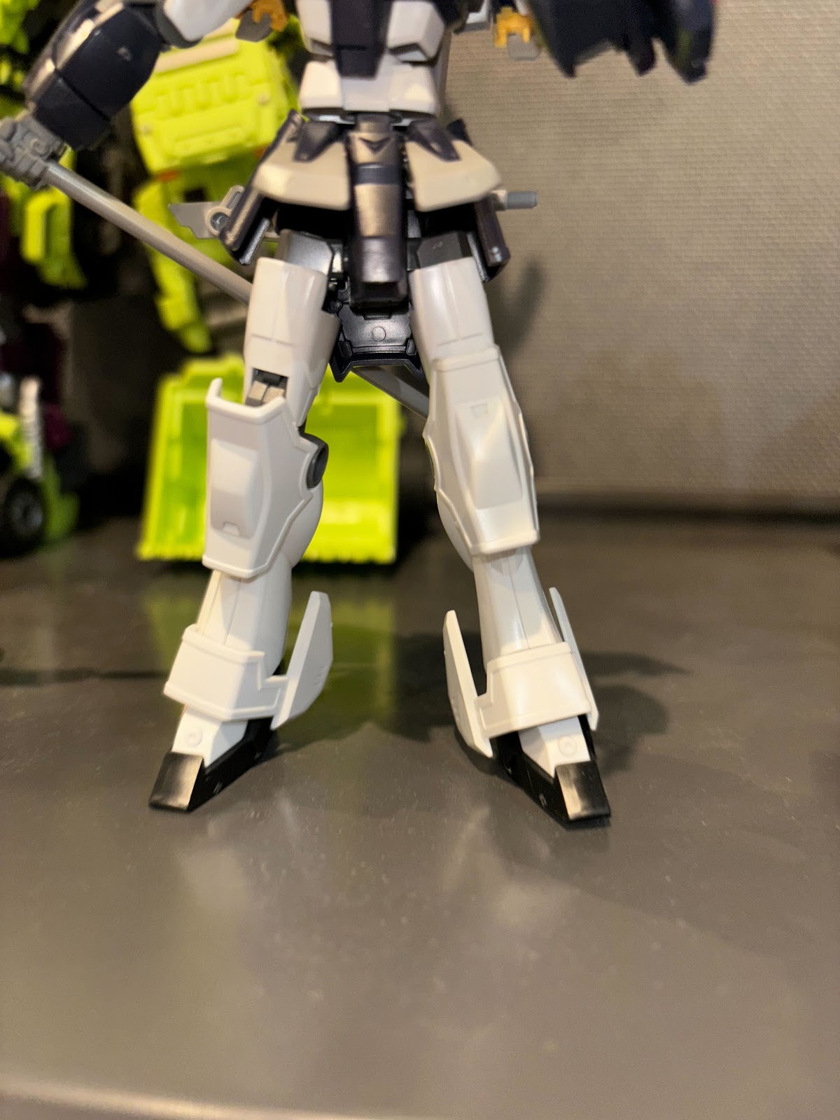
This model includes many of the features I discussed earlier. The feet, while similar in shape to the calves, are separate pieces with an ankle pivot. The toes are on hinge joints with attached pistons, which utilize Track To constraints. Pistons are also used on the hips and shoulders. Hinge and swivel combinations are used for the elbows, and ball and hinge combinations are used for the hands, very similar to how they are constructed on my figures.

For the thighs, I took inspiration from the aforementioned Shockwave figure. His thighs are constructed using sliding armor plates that shift when the knee is bent, which works by attaching the front plate of the thigh to the knee using a pin, along with a curved track. This mechanism works to emulate the movement of muscles in the human leg as it bends and stretches the quadricep muscles. In this robotic character, it fills gaps in the metal plating and also frees up space for the knee to bend further. I used similar shapes for the armor plating when modeling Ironhide's thighs. I also used a Transformation Constraint to shift the front thigh plate as the knee bends, covering up the knee pivot.

Ironhide's torso can bend and swivel on one pivot point, with his armor plates split between the chest and abdomen. The plates have enough wiggle room to get about 15 degrees of rotation in any direction. The armor plating retains its coverage, leaving no major gaps to see the simple mesh inside forming the spine.

A common design among robotic characters is the construction of their waists. In their simplest forms, the pelvis is made up of a t-shaped "underwear" piece, with the abdomen attached to the top and universal hip joints on the side. I replicated these joints on Ironhide. But another common aspect is metal plating that covers the connection points on the waist, resembling armor. Even in action figures this armor plating can be difficult to manage, often popping off of their hinges when the hips are moved. In a 3D model clipping would need to be managed closely. Each piece has its own bone, so they could in theory be rotated out of the way when necessary, but I wanted to streamline the process. Using trusty Transformation Constraints, I mapped the upward motion of the armor plates to the forward, backward, and outward motion of the hip and thigh joints. Now they move out of the way automatically when the leg is rotated. If only real toys had this capability.


I had a similar conundrum with Ironhide's shoulders. I specifically chose this model because he has very bulky shoulders and I wanted to see what I could do with them. Further complicating this is the large hood pieces on either side of Ironhide's head. Clearly they would need to move out of the way if the arms lifted up or rotated. I had to use a combination of 4 Transformation Constraints to lift and rotate the hood pieces if the shoulder rotated in any direction or raised in height. I also made the pauldron pieces lift if the bicep swiveled to the side. In the end I achieved a wider range of motion without clipping in to the hood pieces or head. Because these constraints utilize rig bones, they export into Unreal Engine just fine.

This model uses minimal ball joints, only on the feet, base of each finger, and eyes. Even the head and neck joint is actually a deformed mesh. I feel much more comfortable working with different types of joints after this project.
Conclusion
This research has given me a much greater appreciation of the complex engineering that goes into crafting mechanical beings, both in the real world and 3D modeling. It can be so easy to wave the mechanics of a hard surface piece to the side in favor of visual flair and noise, especially if the final product does not need to move. But learning these principles and integrating them into a design will improve the visual quality of a piece as well. Variety in joint types provides visual interest and helps achieve realism, as it is usually a combination of pivots that bring a complex system to life. And now I feel like I can jump right into modeling these joints with little hesitation, since I know their basic construction and why they are necessary in a specific area. Continuing to practice, I hope to learn of even more complex types of joints, and use them to increase the "wow" factor of my robot characters and props. All in all, they're not too scary, and sometimes it pays to take a closer look at the mechanics of motion all around us.
No comments:
Post a Comment